IN Brief:
- The UFR1002IP monitors voltage, frequency, switching behaviour, and anti islanding conditions.
- Ethernet, Modbus TCP, remote parameterisation, and a 100 event alarm memory support commissioning and maintenance.
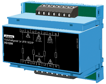
- A VG1200 coupling device extends voltage monitoring to 1,200V applications.
ZIEHL has introduced the UFR1002IP grid and plant protection relay, adding remote access, network communications, detailed event records, and field updatable software to its voltage and frequency monitoring platform.
The device succeeds the UFR1001E and is designed for grid connected generation systems, including wind, photovoltaic, combined heat and power, and other distributed energy installations. It monitors three phase and single phase networks and provides protection against abnormal voltage, frequency, and grid conditions.
A colour LCD and integrated joystick allow settings and measured values to be accessed locally, while the web interface supports parameterisation, diagnostics, alarm review, firmware installation, and application updates without removing the unit from service.
Preset application programmes are provided for different connection requirements. The product carries certification covering VDE-AR-N 4105, 4110, 4120, and 4130 arrangements, together with Great Britain’s G98 and G99 requirements and relevant European connection standards.
The relay monitors undervoltage and overvoltage between 15V and 520V, with a frequency setting range from 45Hz to 65Hz. Additional functions include ten minute voltage quality averaging, vector shift detection, rate of change of frequency monitoring, zero voltage supervision, and passive anti islanding protection.
Its two channel, single fault safe architecture monitors the connected switching device through feedback contacts. Where switch monitoring is enabled, the relay prevents reconnection after detecting a switch off failure, reducing the risk of returning plant to service when the isolation function has not operated correctly.
Response and reconnection delays are configurable, while changes to nominal system voltage automatically adjust the associated switching thresholds. This reduces the risk of retaining unsuitable protection limits when the equipment is transferred between applications or voltage settings.
The alarm memory stores up to 100 events, including the trigger value, cause, date, time, and subsequent restart. An integrated real time clock with power reserve maintains event chronology and supports investigation after disturbances or intermittent trips.
Protection equipment becomes a connected maintenance asset
Distributed generation protection has traditionally concentrated on correct thresholds and dependable tripping, although commissioning time, remote visibility, firmware management, and traceable event data now influence lifecycle performance as well.
Generation plants may operate at remote or lightly staffed sites. A relay that exposes measured values, status information, and alarm history over an authorised connection can reduce preliminary site visits and allow engineers to review conditions before attending.
Modbus TCP communication also allows selected data to be integrated with supervisory control, plant monitoring, or maintenance systems. Its value depends on disciplined point mapping, time synchronisation, alarm priorities, and separation between monitoring functions and commands capable of altering protection behaviour.
Remote access introduces corresponding responsibilities. Network segmentation, user permissions, password management, change records, firmware validation, and secure service routes need to be incorporated within the wider plant cybersecurity architecture.
Protection settings remain an engineering responsibility even where preset programmes reduce commissioning time. The selected profile must correspond with the connection agreement, network operator requirements, generating unit characteristics, switchgear, transformer arrangement, and behaviour of the complete installation.
Automatic threshold adjustment following a nominal voltage change reduces one source of parameter error, but verification is still required. Secondary injection testing, switch feedback checks, trip time measurement, reconnection logic, and confirmation of approved settings remain part of commissioning.
The UFR1002IP includes test and simulation functions capable of measuring switch off times, allowing the complete trip chain to be checked rather than the relay output alone. Breaker or contactor operation, wiring, auxiliary supplies, feedback contacts, and mechanical travel all contribute to final disconnection performance.
Higher inverter voltages are widening the measurement range required in larger generating systems. When combined with the VG1200 coupling device, the relay can monitor voltages up to 1,200V without a conventional voltage transformer.
Displayed values and protection limits are scaled to represent the voltage at the coupling device input. The arrangement supports installations using higher inverter or internal collection voltages to reduce current and conductor losses.
Higher voltage can improve electrical efficiency, but insulation coordination, clearances, switching equipment, test procedures, and protection measurement must all match the revised system design. The coupling device cannot compensate for unsuitable equipment elsewhere in the installation.
Digital event records are also becoming standard at network level. The Freidorf substation modernisation replaced electromechanical relays with connected protection and control equipment across a 110/20kV installation.
The UFR1002IP applies a similar direction at the generation connection interface, where more information is available locally and remotely and software plays a larger role in commissioning and service.
The underlying protection duty remains unchanged. Abnormal grid conditions must be detected accurately, the correct switching device must operate within the required time, and reconnection must occur only when the network and generating plant are ready.