IN Brief:
- A southwest China renewable-energy base used a Flir T540 across modules and electrical equipment.
- The dual field-of-view lens switches between 24° and 14° views without lens removal.
- Thermal patterns require operating context and secondary tests before maintenance decisions are made.
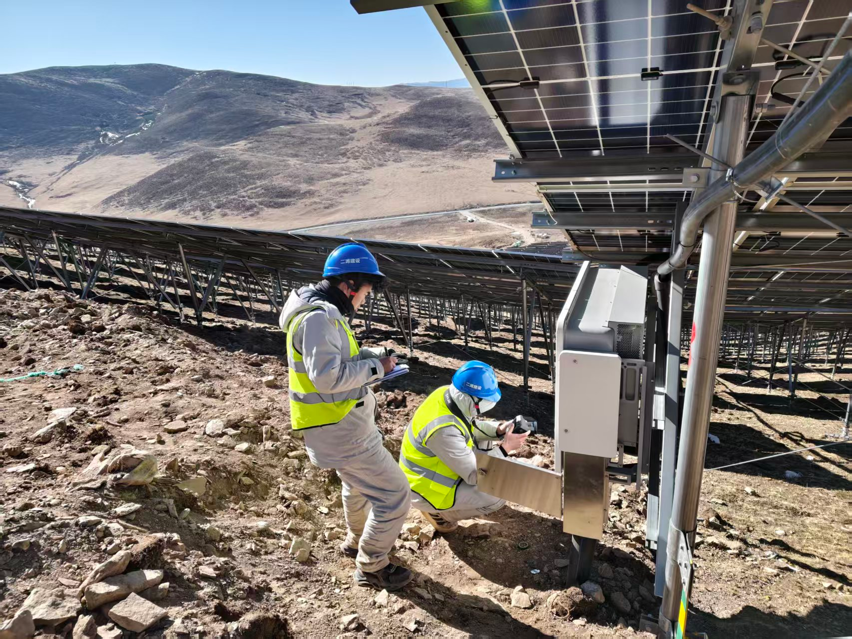
An unnamed 80GW hydro-wind-solar base in southwest China has used a Flir T540 thermal camera with a dual field-of-view lens across photovoltaic modules, electrical equipment, support structures, and transmission connections.
The case study, supplied by Flir, presents infrared inspection as part of a shift from reactive fault-finding towards condition-based maintenance. The operator is not identified, and no independently audited performance dataset is provided, so numerical results should be treated as supplier-reported outcomes rather than general benchmarks for other sites.
Switching between survey and detail
The T540 uses a 464 × 348-pixel infrared detector and can be paired with a FlexView lens that switches between 24° and 14° fields of view without being removed from the camera. The wider setting supports scanning across larger areas, while the narrower telephoto view can isolate smaller or more distant temperature anomalies.
That combination is relevant at utility-scale photovoltaic sites, where inspectors may need to cover extensive module tables before examining individual components, cable joints, inverters, transformers, or support equipment. Changing conventional lenses interrupts the inspection route, increases handling, and can make it harder to maintain a repeatable camera configuration.
The narrower view can also support inspection from a greater distance, provided the target occupies enough detector pixels for a meaningful reading. It does not replace safe-working distances, arc-flash controls, permits, barriers, or other electrical precautions.
Thermal imaging does not identify an electrical defect directly. It maps surface temperatures that may indicate resistance, current imbalance, defective cooling, shading, cell damage, poor contact, or diode failure, leaving the thermographer to determine whether the pattern is abnormal under the prevailing operating conditions.
Interpreting module anomalies
Flir reports that the maintenance team used temperature differences greater than 5°C to identify photovoltaic hot spots associated with shading, damage, or diode problems. The supplier says affected modules could then be prioritised for intervention within 24 hours, with potential power losses of between 20% and 50% avoided.
Those figures describe the reported case and should not be treated as universal thresholds or savings. The significance of a temperature difference depends on irradiance, wind, module current, reflected temperature, viewing angle, emissivity, and the comparison being made with neighbouring cells or modules.
A useful inspection links the thermal pattern with visual examination, string current, voltage data, inverter monitoring, and the operating history of the affected module. Without that context, a hot area caused by temporary shading or uneven irradiance can be mistaken for an electrical defect.
The case study also describes linear or mesh-shaped cooler patterns, with differences of around 1°C, as possible indicators of micro-cracks or cold-solder joints. Identifying variations of that scale requires stable conditions, suitable measurement distance, adequate spatial resolution, and disciplined image interpretation.
Transient cloud, wind, dirt, and rapidly changing electrical load can produce small temperature differences that resemble defects or conceal them. Electroluminescence testing, current-voltage tracing, or more detailed electrical measurements may therefore be needed before replacing a module.
Potential-induced degradation is described as producing stripe-shaped warmer areas along module edges. PID can reduce performance where voltage stress contributes to leakage currents between cells and the grounded frame or glass structure, but thermal imaging again serves as a screening method rather than a complete diagnosis.
Inspection beyond the module field
The programme extended to inverters and transformer boxes, where warm terminals or heat sinks can indicate loose connections, overload, phase imbalance, restricted airflow, or deteriorating components. Infrared inspection is particularly useful when equipment remains energised and carries representative load, because a poor connection may appear normal when isolated and heat rapidly under current.
Battery banks were checked for localised overheating and abnormal temperature rise, while insulated busbars were inspected for patterns associated with poor contact or ageing insulation. Static-var-generator modules, reactors, incoming cables, and cable joints were also included.
Each asset requires its own reference conditions. Comparing equipment at different loads, unlike components, or phases carrying substantially different current can turn a technically accurate temperature measurement into an incorrect maintenance conclusion.
The team also used thermal imaging on support structures and mechanical connections. Temperature anomalies may reveal friction or abnormal loading in some mechanical systems, although deformation or loose components should be confirmed by physical inspection rather than inferred from infrared data alone.
At transmission connections, temperature comparison between similar phases and joints can help identify local resistance or overload. The finding becomes more useful when it is linked with current measurements and previous surveys showing whether the anomaly is stable or worsening.
Turning images into maintenance evidence
The practical value lies less in collecting infrared photographs than in creating a repeatable inspection process. Survey routes, ambient conditions, camera settings, load information, asset identifiers, alarm criteria, and follow-up actions must be recorded so that images taken at different times can be compared.
Integration with supervisory control and data acquisition systems can improve prioritisation. A module anomaly accompanied by falling string current, an inverter terminal heating as load increases, or a cable joint showing a worsening trend provides stronger maintenance evidence than an isolated image without operating data.
The supplier says the deployment supported a “proactive prevention” strategy and reduced inspection time and operating costs. The case study does not publish baseline labour hours, failure rates, avoided downtime, measurement uncertainty, or a methodology for calculating those savings.
Its strongest evidence is therefore the breadth of the application. One inspection platform was used across modules, conversion equipment, battery systems, conductors, support structures, and grid connections, with the dual field-of-view lens reducing the need to change optics between wider surveys and more focused checks.
The camera’s published accuracy is ±2°C or ±2% of the reading, while the detector and lens determine how small a distant target can be measured reliably. That specification reinforces the need to distinguish between detecting an apparent anomaly and assigning a precise temperature to a small component at range.
Training remains the decisive element. Inspectors need to understand reflected radiation, emissivity, weather, loading, spatial resolution, and the limits of non-contact measurement, while maintenance engineers need defined rules for verification and intervention.
For large photovoltaic operators, thermal imaging can make condition monitoring faster and more targeted. Without controlled survey conditions and secondary testing, however, it merely creates a larger archive of colourful images — and power stations already generate quite enough data that nobody has time to interpret.